



ECG Electrode Placement Guide: 3-Lead and 5-Lead Positioning

Written by Dallas Akins
Quick Answer: For a common 3-electrode monitoring setup, place RA and LA electrodes on the upper right and upper left torso, and the LL electrode on the lower left torso. A common 5-electrode setup adds RL on the lower right torso and one chest electrode, often labeled V or C, in the location specified by the monitor, facility protocol, and clinical purpose. Confirm the labels and instructions for the exact cable in use; AHA and IEC color codes differ, and bedside monitoring placement differs from a diagnostic 12-lead ECG.

Correct ECG electrode placement helps a monitor capture a stable electrical signal. Even a small change in position, poor skin contact, or a mismatched lead wire can alter the waveform or create artifact. For nurses, EMTs, home-health aides, and trained caregivers, a repeatable placement process is therefore an important part of reliable ECG monitoring.
This guide covers common 3-lead ECG placement and 5-lead ECG placement for bedside or portable monitoring. It does not explain how to interpret an ECG or diagnose a rhythm. Always follow the monitor manufacturer’s instructions, your organization’s protocol, and the direction of the responsible clinician.
Electrodes, Lead Wires, and Leads: What Is the Difference?
These terms are often used interchangeably in searches for ECG placement or EKG lead placement, but they describe different parts of the setup:
Electrodes are the adhesive conductive patches placed on the skin.
Lead wires connect the electrodes to the ECG cable or monitor.
A lead is an electrical view of the heart created from the voltage difference between electrodes.
A 3-electrode system can display three bipolar limb leads—Lead I, Lead II, or Lead III—depending on the monitor and selected setting. A 5-electrode system adds a reference electrode and a chest electrode with a position selected for the monitoring objective. The number of electrodes is not always the same as the number of ECG views displayed.
Before ECG Electrode Placement
Prepare the equipment and skin before attaching the lead wires. A consistent setup reduces avoidable artifact and helps electrodes remain attached.
Verify the monitoring order, cable type, and selected mode on the device.
Identify each wire by its printed label—RA, LA, RL, LL, and V or C—not by color alone.
Explain the process, provide privacy, and position the person comfortably with the torso accessible.
Choose intact, dry skin away from prominent bone, large muscles, skin folds, irritated areas, and locations that will be rubbed by clothing or equipment.
Remove excess oil, lotion, sweat, or debris and allow the skin to dry. Clip excess hair if needed; do not shave unless required by local protocol.
Use fresh, compatible electrodes and check the package expiration date. Replace dried or poorly adhering electrodes.
Connect the lead wires without pulling on the electrodes, and arrange the cable to reduce tension and movement.
3-Lead ECG Placement
In a common torso configuration for 3-lead ECG monitoring, three electrodes form a triangle around the heart. Place the electrodes symmetrically and use the same landmarks each time.

Keep RA and LA at comparable heights and LL well below them to maintain a clear triangular arrangement. Avoid placing an electrode directly over the clavicle, ribs, or a large muscle. Once connected, confirm that the monitor recognizes the electrodes and that the tracing is stable before relying on the displayed signal.
5-Lead ECG Placement
A 5-electrode monitoring system uses four limb-labeled electrodes on the torso plus one chest electrode. The four torso positions provide a stable reference around the heart. The chest-electrode position may vary with the monitoring objective and local protocol, so it should not be chosen from memory when the device instructions specify a location.

How to locate the common V1 chest position
If the prescribed configuration uses V1, locate the sternal angle, identify the second intercostal space, and count downward to the fourth intercostal space. Place the chest electrode immediately to the right of the sternum. Do not estimate the intercostal space from the nipple line, which varies between individuals.
Other chest positions may be used for specific monitoring goals. Use the chosen position consistently, document it as required, and do not move the chest electrode without checking the applicable protocol.
Do Not Rely on Wire Color Alone
The American Heart Association (AHA/AAMI) and International Electrotechnical Commission (IEC) systems use different colors for the same electrode labels. A wire that is red in one system can represent a different position in the other. Read the letters printed on the connector or lead wire before placement.

Common ECG Placement Errors
The following chart highlights common ECG placement errors and the steps that can help prevent them.

Why Correct Placement Matters for Signal Quality
An ECG monitor measures very small voltage differences at the skin. Secure contact, consistent landmarks, and correct wire assignment help reduce motion artifact, baseline movement, and false “lead off” messages. Correct placement also makes repeat recordings more comparable.
If the tracing looks unstable, first check the person and follow the appropriate clinical response. Then verify electrode adhesion, skin condition, cable connections, wire labels, and lead placement. Do not assume every unexpected waveform is only a placement problem, and do not use this guide to interpret the tracing.
Using ECG Placement Guidance With the CMI PC-303
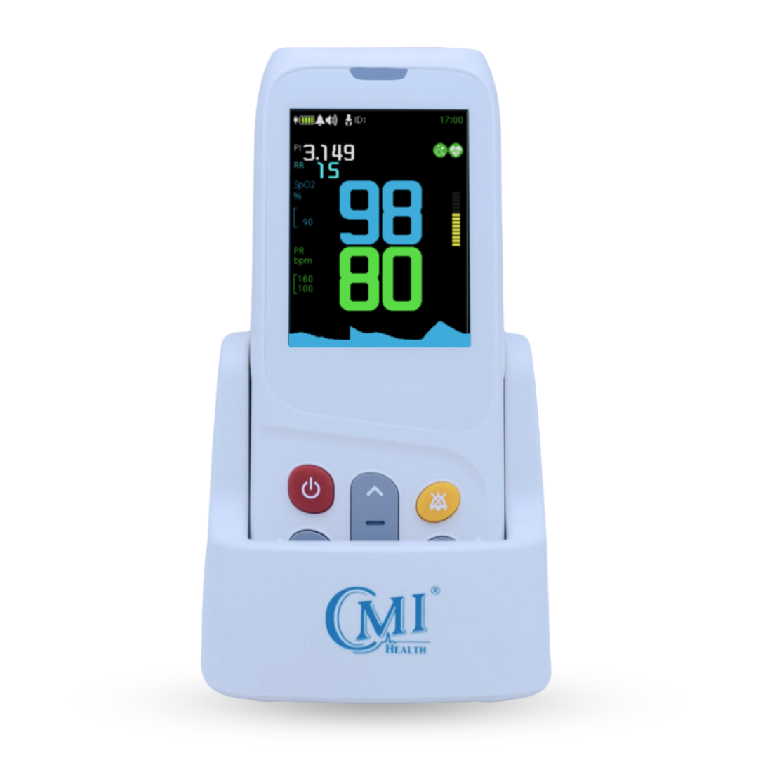
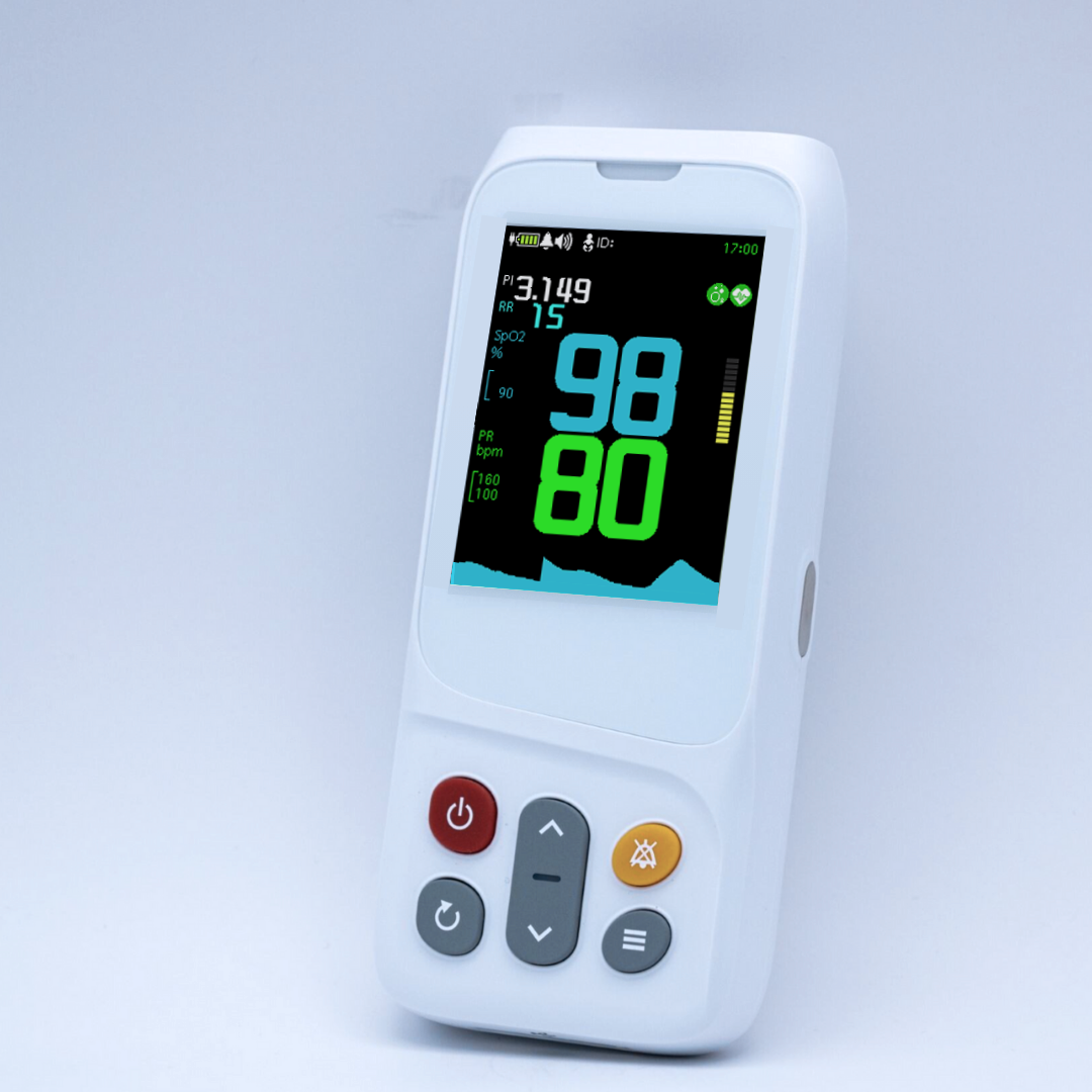
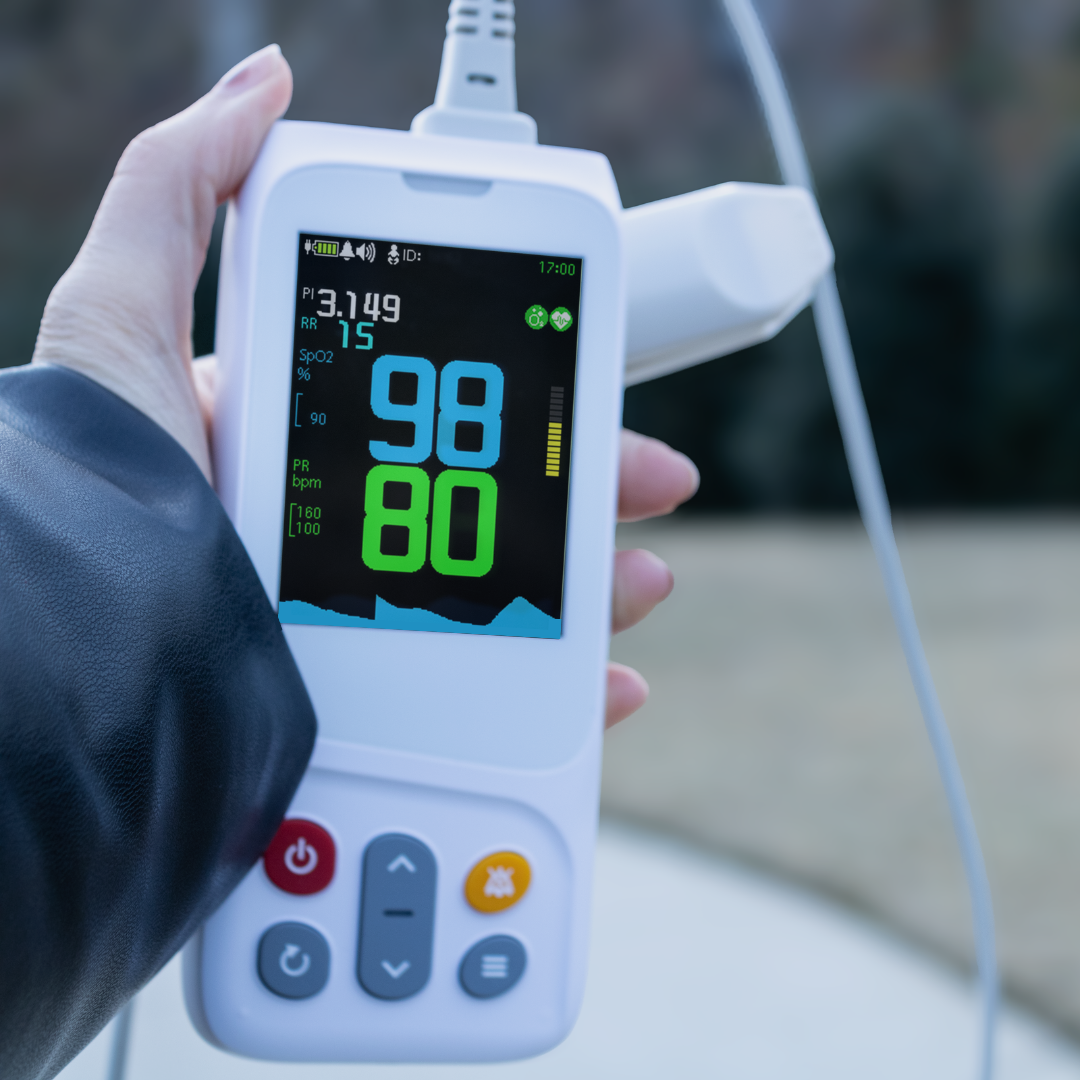
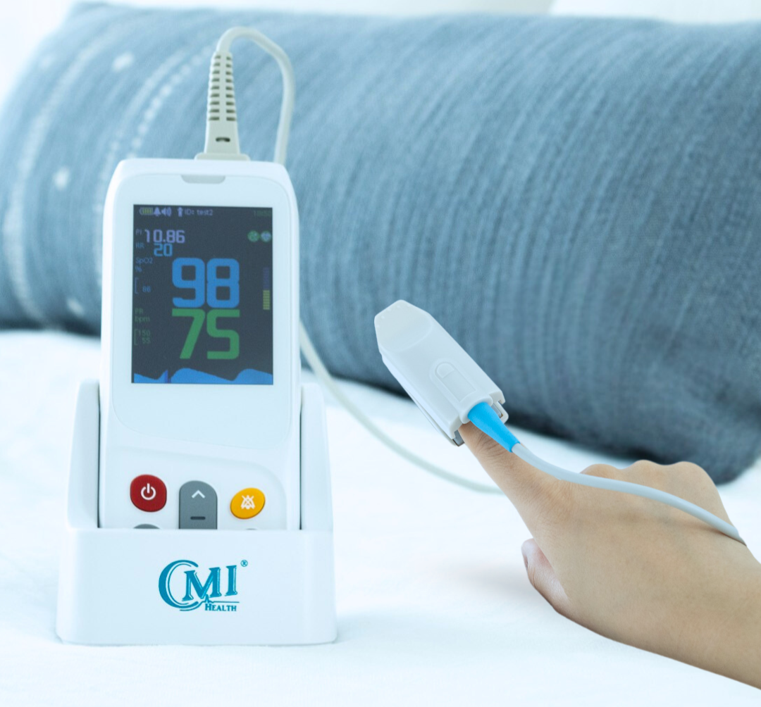
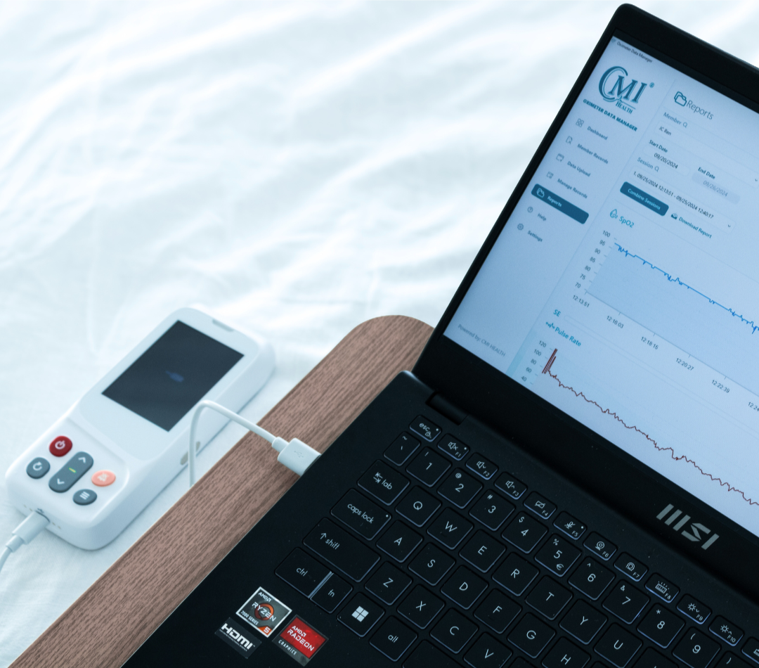
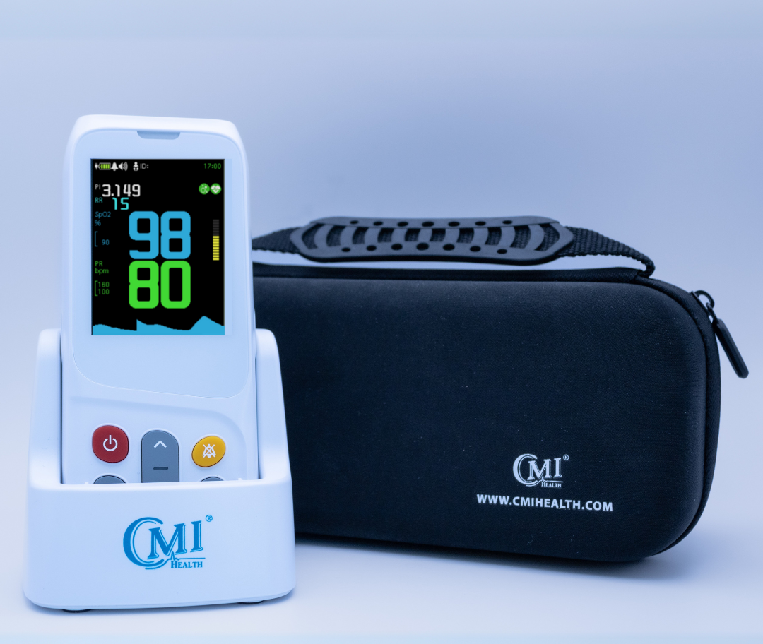
The CMI PC-303 Telemedicine Vital Sign Monitor (SKU PC-303H) provides single-channel ECG measurement in two modes: 1-lead measurement using the monitor’s embedded electrodes and 3-lead measurement using a compatible lead wire. For a broader overview of its measurements and display, see How to Read a Vital Signs Monitor.
When using the PC-303H in 3-lead mode, follow the 3-lead placement guidance above along with the device instructions. The 5-lead placement information in this guide applies to monitoring systems designed for a 5-electrode configuration.
Always use accessories approved for the specific monitor and follow the manufacturer’s operating instructions.
Quick ECG Electrode Placement Checklist
- Confirm the device, cable, monitoring mode, and ordered configuration.
- Identify each lead wire by its printed label rather than color alone.
- Prepare clean, dry, intact skin and use fresh compatible electrodes.
- Place upper and lower electrodes using consistent anatomical landmarks.
- For a 5-electrode system, verify the required V/C chest position.
- Secure and route the wires to reduce tugging and movement.
- Check for a stable signal and correct any lead-off or artifact message.
- Document altered or nonstandard placement according to protocol.
Frequently Asked Questions
Is 3-lead ECG placement the same as a 12-lead ECG?
No. Three-electrode torso placement is commonly used for basic cardiac monitoring. A diagnostic 12-lead ECG uses ten electrodes placed at standardized limb and chest landmarks to generate twelve views. Do not apply bedside torso positions to a diagnostic 12-lead recording unless the approved procedure specifically calls for a modified configuration.
Where does the fifth ECG electrode go?
The fifth electrode is the chest electrode, labeled V in the AHA/AAMI system or C in the IEC system. Its position depends on the device, protocol, and monitoring goal. V1—the fourth intercostal space at the right sternal border—is one common position, but it is not the only possible monitoring position.
Why does ECG lead placement use different colors?
Two major color conventions are in use. AHA/AAMI and IEC assign different colors to RA, LA, RL, LL, and V/C. Because colors can be misleading, match each printed label to the correct position and consult the device instructions.










Leave a comment